Projects
About Me
Find Me
Portfolio
All Posts:
- Ham Radio: 9:4:1 Impedance Matching with a Homemade Autotransformer
- RISC Processor, Custom ISA, and compiler
- Newspaper Article: Competing in Science Olympiad
- Newspaper Article: Hosting a Learn to Solder Day at LASA Electronics Club
- Animated LED map of territorial expansion in the modern day German region + Road trip!
- Another Blog Post About This Blog (updates!)
- Updates and Future of the Blog
- MathMl: Easy Embedded Math in HTML (No extra libraries, browser supported!)
- Raymarching: Perfect Spheres and Easy 3D
- Never Write a Line of CSS Again
- Jinja is Awesome
- A Blog Post About This Blog
Ham Radio: 9:4:1 Impedance Matching with a Homemade Autotransformer
4-5-2026
In order to get back on the air at my house, I put together this autotransformer with taps for 9:1 and 4:1 impedance matching based on a design my friend had build in the past. It is designed to go along with a random wire antenna. I'll document it here and write a bit about my experience building it.
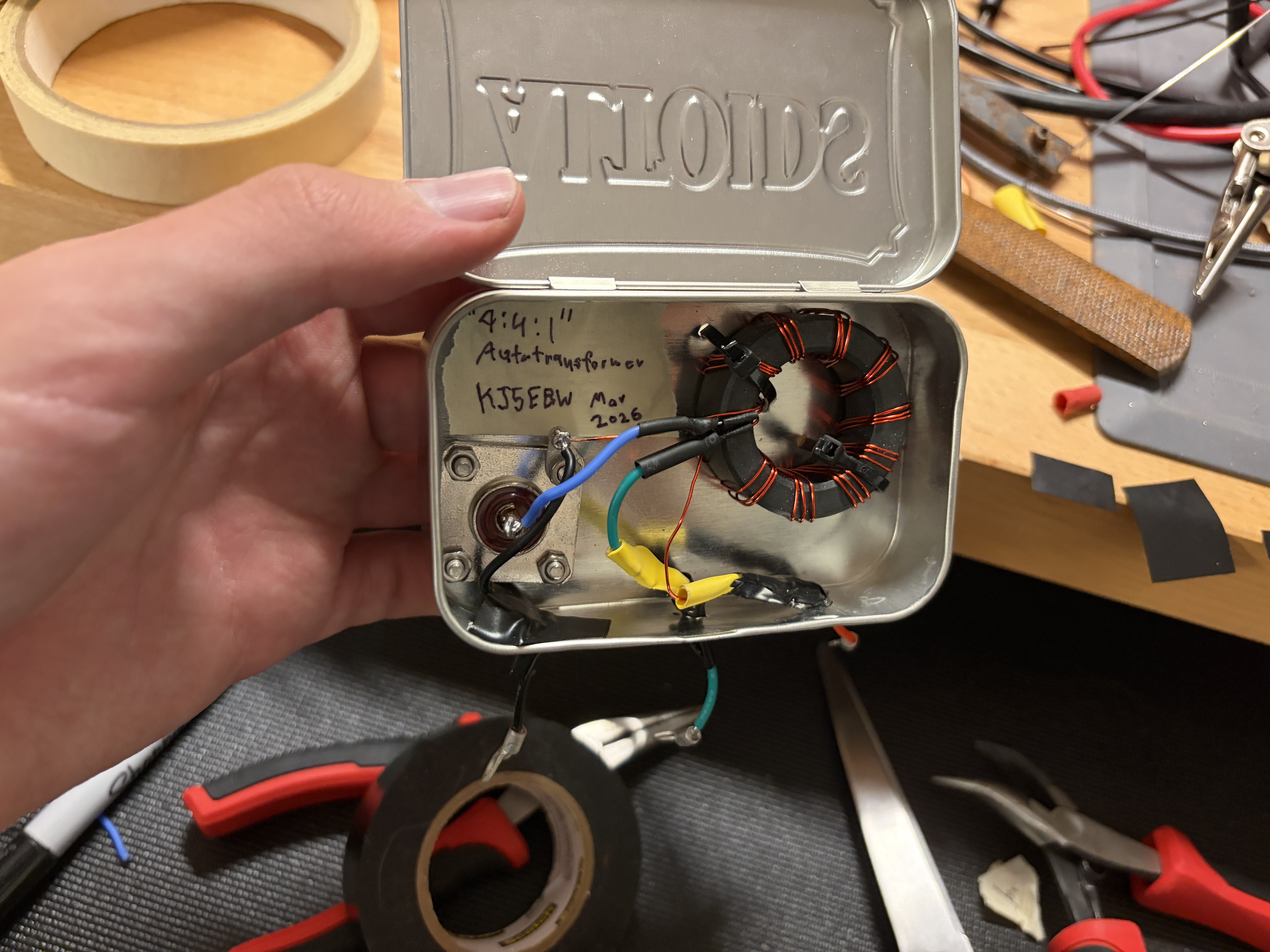
Completed autotransformer
Very basic theory
The goal of this transformer and any other impedance matching network is to make a load impedance (of an antenna in this case) act like a different impedance (50 ohms for most ham radio stuff) to a given source (radio) in order to minimize reflections and maximise power transfer.
You don't need to understand all of the theory in order to make on of these, but it is nice to know. The equation for impedance matching with any transformer can be derived with the following given two coils with turns N1 and N2, a voltage and current across each of V1, V2, I1, and I2, and a source and load impedance of Z1, Z2 (note that the voltage and current across the second coil is equal to the voltage and current across the load):
-
V1 / V2 = N1 / N2(transformer law) -
I1 / I2 = N2 / N1(transformer law) -
Z2 = V2 / I2(definition of impedance) -
V2 = V1 / (N2 / N1)(from eq. 1) -
I2 = I1 / (N1 / N2)(from eq. 2) -
Z2 = (V1 / (N2 / N1)) / (I1 / (N1 / N2))(sub into eq. 3) -
Z2 = (V1 / I1) * (N2 / N1)^2 -
Z2 = Z1 * (N2 / N1)^2(definition of impedance) -
Z1 = Z2 * (N1 / N2)^2
In this way, a transformer can be used to make a load impedance of Z2 act like an impedance of Z2 * (N1 / N2)^2. While this project is an autotransformer which only uses one wire (the primary and secondary will "share" a section of wire), the theory still applies as it still acts like segments of wires with a shared magnetic core.
This project uses turn ratios of 10/20 and 10/30 which you can select between, giving impedance ratios of 9:1 and 4:1 (hence the 9:4:1 name). A wire is wrapped in 10 turns going all the way around a toroid three times (giving 30 total turns). As seen in the schematic below, the 50 ohm input is connected to a 10 turn "primary", the 200 ohm input to a 20 turn "secondary", and the 450 ohm input connected to a 30 turn "secondary".
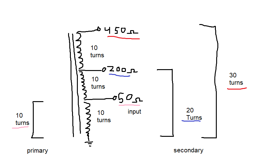
Electrical layout of the autotransformer
Construction
I had a stockpile of Altoids tins and wanted to try and fit one in here. I decided to use a FT140-43 toroid for the core (FT=ferrite, 140=1.4in OD, 43=mix type) as I typically operate from 40m-10m, but most toroids will do alright. My friend who had also build one of these had just used a random powdered iron toroid he had pulled out of an old audio amp. I had everything else in stock so this was a pretty easy project to get started on.
I started by drilling the holes for the SO-239 UHF connector. I had to use a stepped drill bit for the first time which ended up just lifting the aluminium to the sides so I had to go over and cut that down with a Dremel.
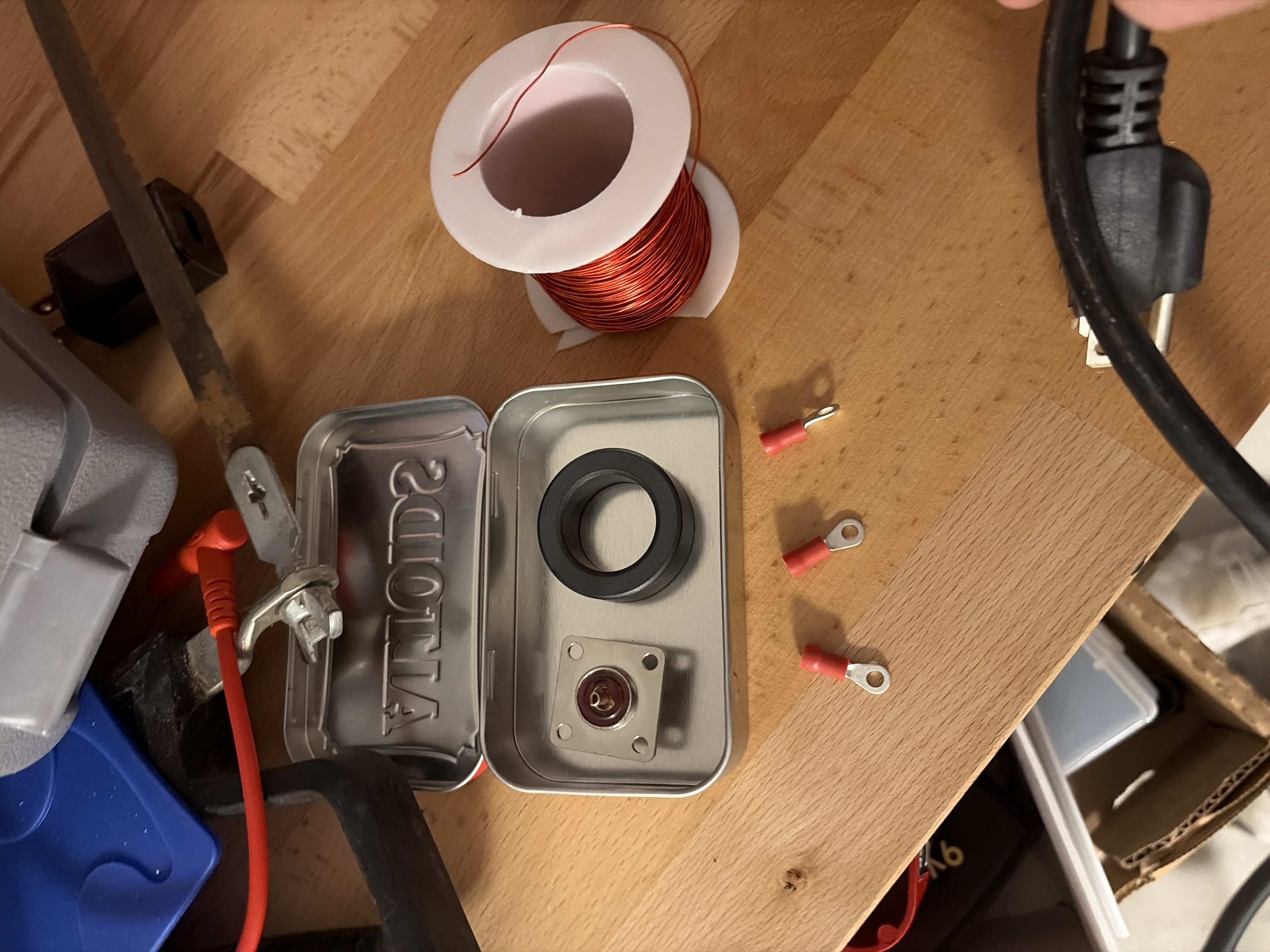 Making sure everything fits nicely
|
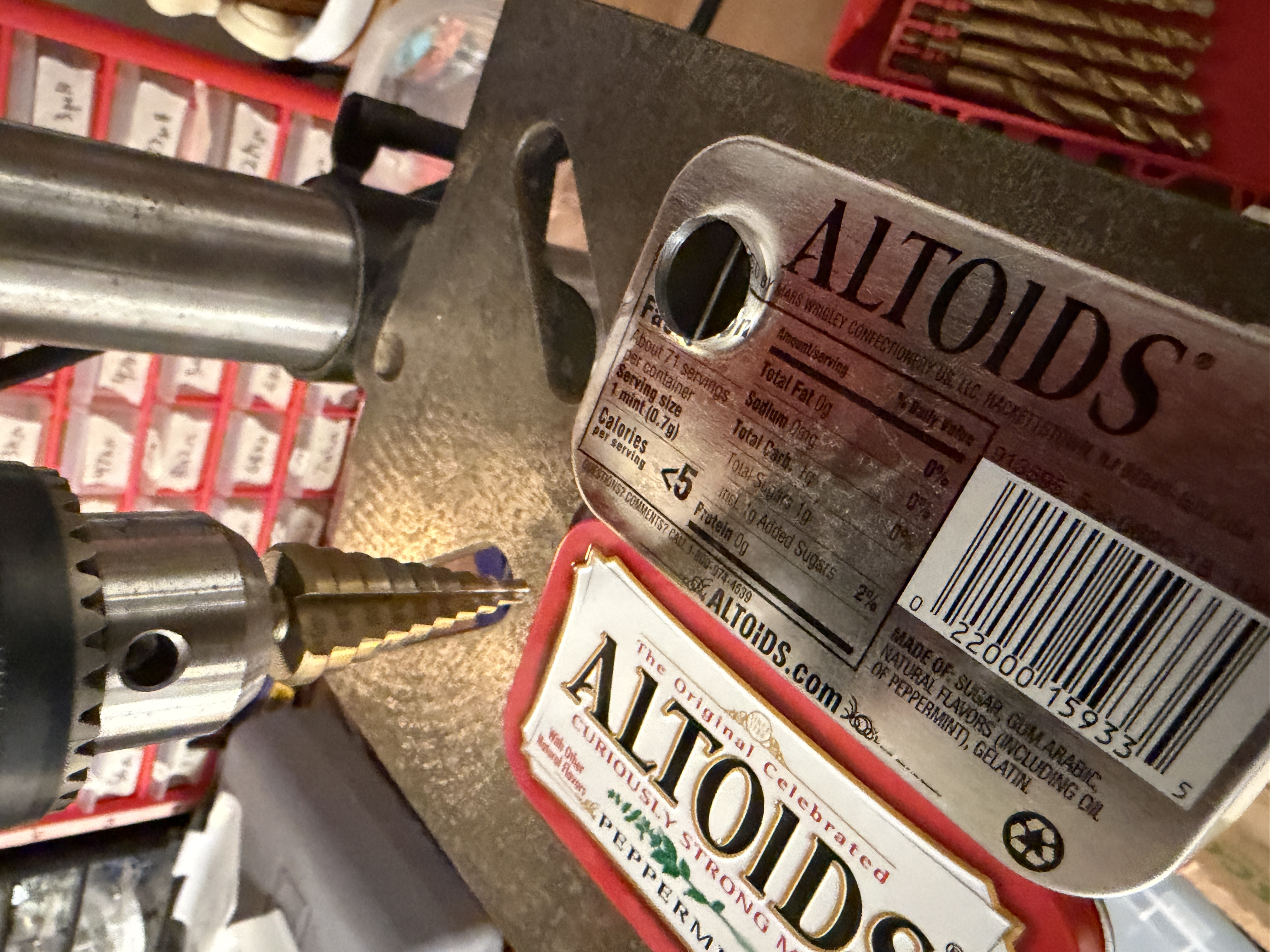 Sides of the SO-239 connector hole lifted up by the stepped drill bit
|
Winding the transformer
I used 0.5mm (24 gauge) enameled copper wire to wind the transformer, removing the enamel on the ends with sand paper once they were in place around the toroid. To make it easier to tap each point, you should wind three separate piece of wire around 10 times each and then only connect them at the end to form the total 30 turns. When I made mine, I put the turns for one full winding close to the turns for another full winding in order to make it easier to do the right amount of turns, but this is not required (this is why you can see groups of three wires on each crossing).
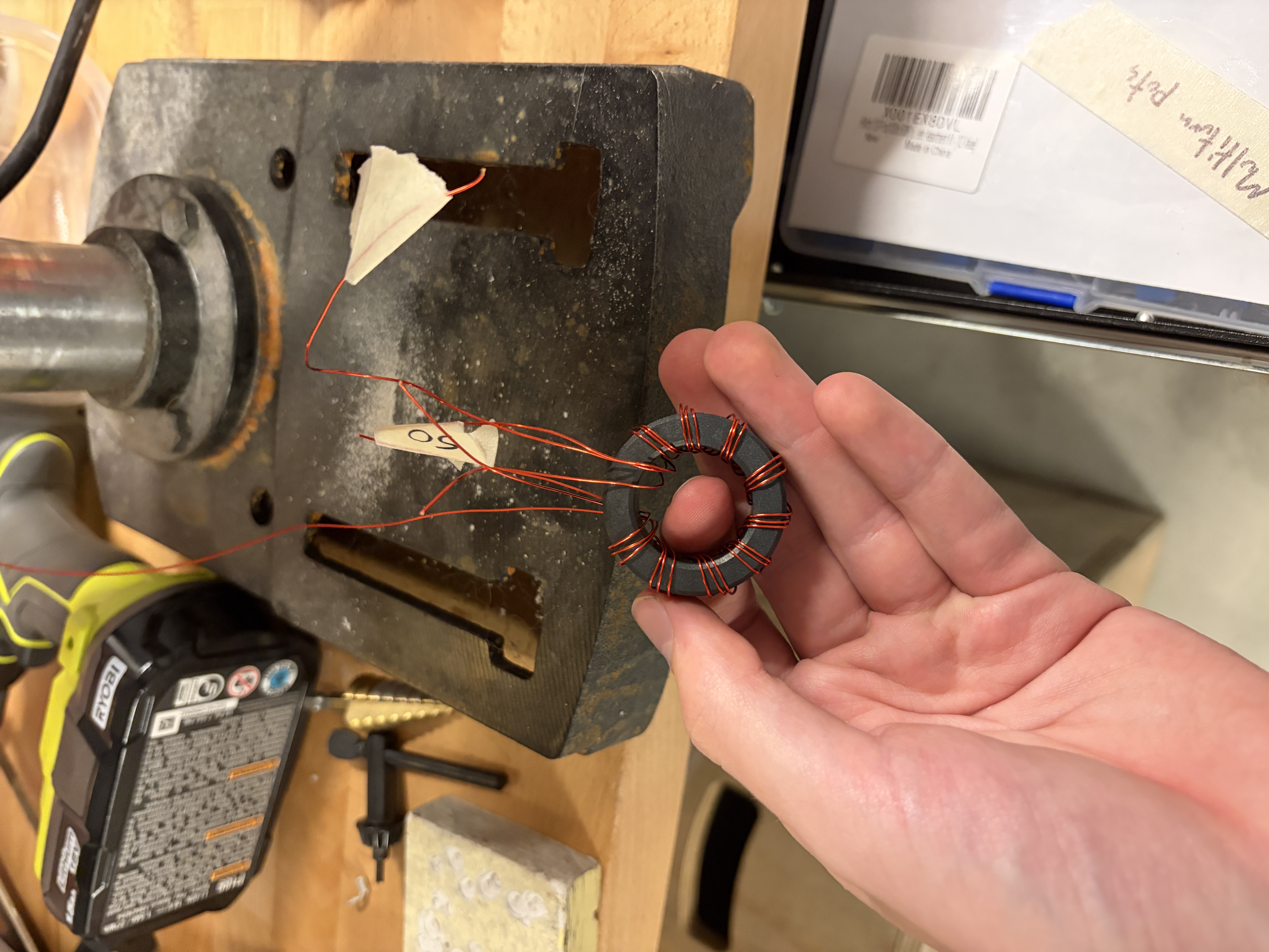 Initial winding of the toroid
Case
Once everything was wound, I temporarily mounted the core in the case with masking tape and soldered all of the connections. In an attempt to provide some strain relief on the wires, I first soldered them to wire terminals inside of the container and then soldered an external wire to the other end of the wire terminals and wrapped the whole thing with heat shrink. The idea was that these would get caught on the sides of the tin, but now all of the stress is just on the solder joint to the wire terminal. I will likely invest in some real strain relief connections in the future. Since all of my antenna wires are terminated in wire terminals which I use screws to connect to, I added wire terminals to the ends of the wires. Once everything was in place, I drilled some extra holes and used zip ties to hold the core down.
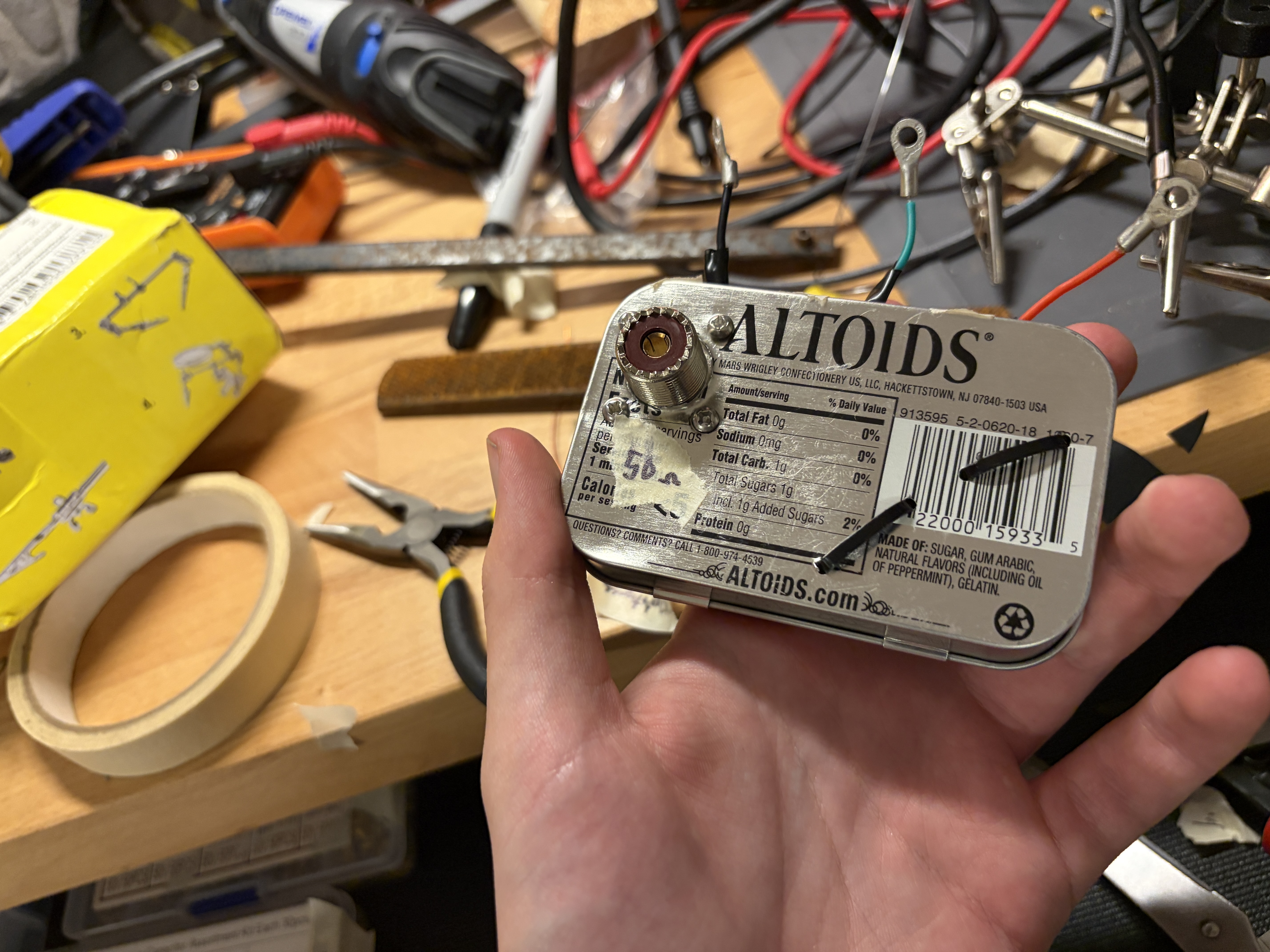 Bottom of the case with the SO-239 connector and zip ties visible
|
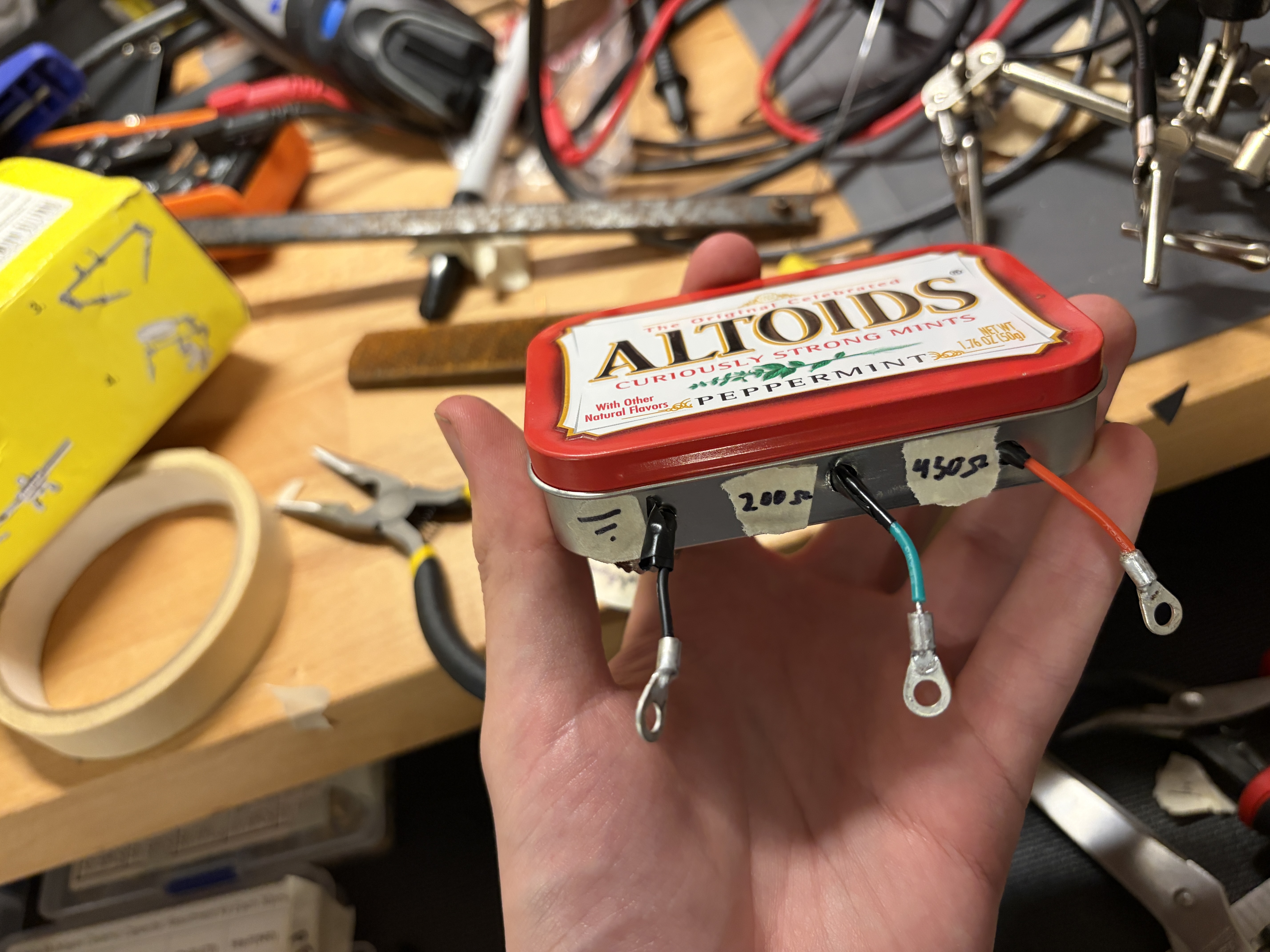 Front connections using wire terminals
|
Testing + antenna
Although I did not take pictures, I tested the response to 200 and 450 ohm resistors on the 4:1 and 9:1 terminals using a NanoVNA and it was able to match pretty spot on to 50 ohms for both.
For the random wire antenna, you can use 35.5' or 16.5' wire for the main element and 6.5' or 3.5' wire for the counterpoise (in various configurations depending on your frequency and physical setup). I've been having good luck on 40m at night with the 35.5' sloped out of my window and the 6.5' wire sloped upwards in my room using the 450 ohm port, but you can play around with different combinations as seems fit. I've been able to get a couple dozen FT8 contacts using it over a couple of nights and have pushed it to 50W without any noticeable heating (I would recommend not going much above 30W for digital modes or 100W for SSB with the same FT140-43 core as I'm using in order to avoid damaging the core). You will likely need to use another impedance matcher after this to get a low enough SWR but this unit can get the initial impedance close enough to 50 ohms that it is relatively easy to match with a simple network or a radio's built-in ATU.
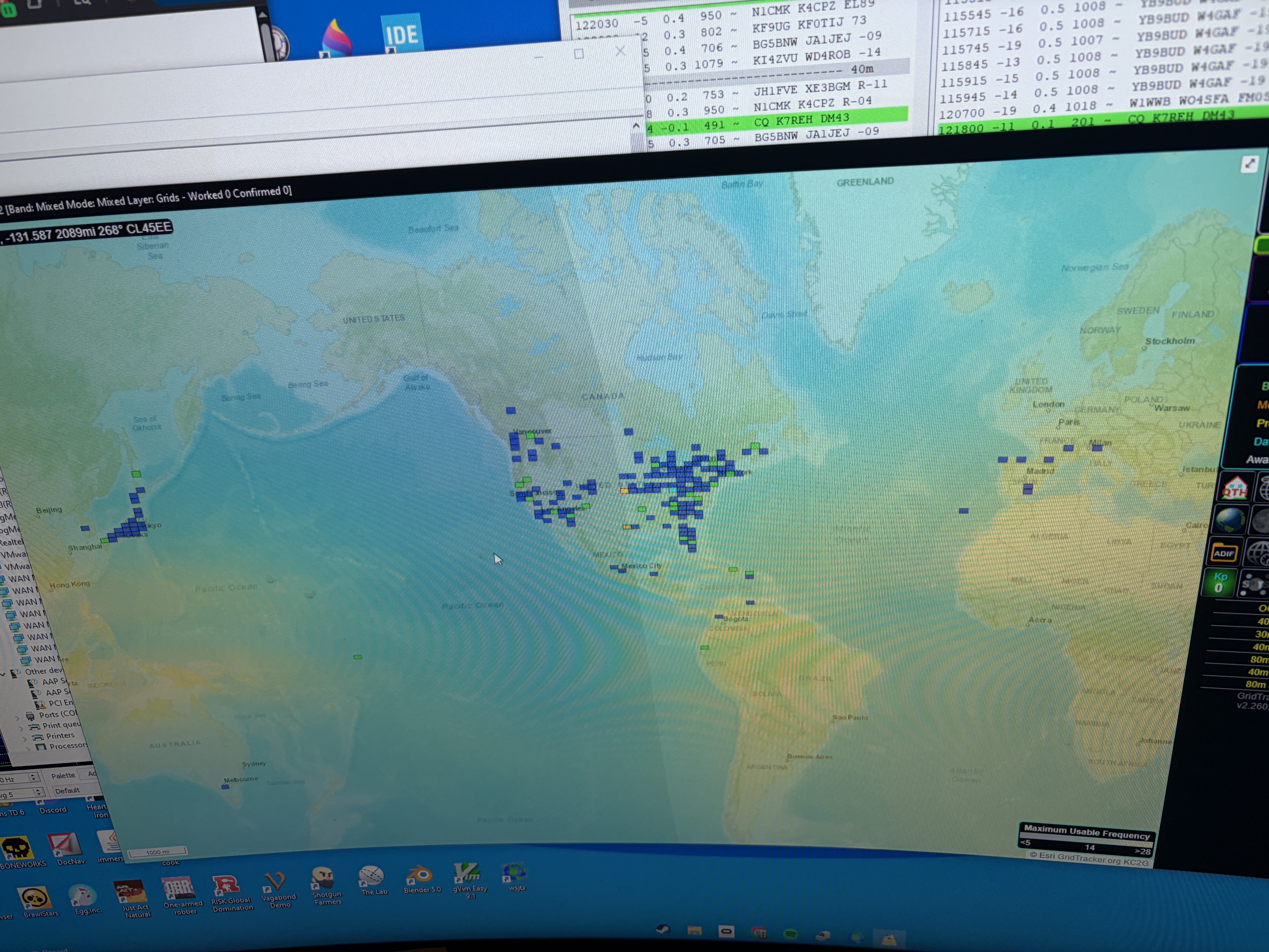 Locations of stations heard while listening to FT8 overnight on 40m using a 35.5' wire sloping out of my window connected to the 450 ohm terminal and a 6.5' wire connected to the ground terminal. Got just about all of Japan! Picture taken of GridTracker2 software.
Comments
Post a comment:
Please don't spam the comments, I get a notification every time. Also please be mature (Nolan)
Message limit: 1500 characters, name limit: 100 characters
No comments here yet. You should write one!